Superflex Wide Arch Design Rubber Expansion Joint

Style 1000 Features and Benefits
Versatile, reliable and economic solutions to your piping needs
Delivers twice the movement allowances than standard arch construction
Double reinforced construction provides longer joint life expectancy
Hand wrapped custom built construction to allow for design variations, while still offering wide arch movement
Suited for temperatures in excess of 350°F (176°C) depending upon service, reinforcement, and compound
Exceptional directional movement absorption capabilities
Available in a full range of elastomers to enable multi-purpose applications
Construction provides woven polyester fabric and reinforced wire to create superior performance characteristics
Standard and custom dimensions available
Supports a piping system pressure range of 85 Psig to 225
Standard and additional drilling available including Navy, ANSI, Metric and JIS
Tube and cover materials available in: EPDM, Natural Rubber, Buna-N/Nitrile, Silicone, Neoprene, Gum Rubber, CSM, PTFE/FEP/TFE, Butyl, SBR/GRS/Buna-S, Viton®/Fluorel and Chlorobutyl
Reinforcement Materials and Compatibility: Polyester, Fiberglass, Nomex, Nylon, Rayon and Kevlar®
Superflex Joints can be specially constructed for vacuum service and can be reinforced for higher pressure applications (SEE Style 200XL).
Super-Flex Style 1000 and 1100 Dimensions and 150# Drilling ANSI, Metric and Special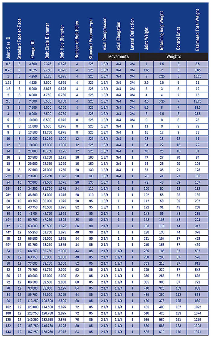
l Drilling Information
All Super-Flex Expansion Joints have a minimum 3 to 1 safety factor at rated operating temperatures and pressures. To conform to ASTM F1123-87 Standards, which require a minimum 4:1 safety factor, you must reduce the above working pressures by 25%
Directional Movement Absorption
A major engineering concern in any rigid pipe system involves directional movements caused by thermal expansion. When a piping system is in use the temperature increases the internal and external surfaces of the alloys that make up the piping structure expanding the pipe, and causing the system to deform in a 3-Dimensional field.
To explain the 3-D Field we will call the axis that runs along the ID/OD of the joints and pipe system as the “X” axis the axis of movement perpendicular to the “X” in a north/south direction if the “Y” axis and the axis perpendicular to the “X” in an east/west direction if the “Z” axis. These movements can be defined as:
Axial Compression: Axial compression is defined as the movement along the “X” axis which follows the Internal Diameter of the pipe itself causing a decrease in the spacing between two segments of the pipe. This decrease is spacing places undue compression stress on the area between the two segments. The flexibility of the Polymer based expansion joint absorbs this compression stress and protects the metal pipe on either end.
Axial Elongation: Axial Elongation is the opposite reaction of the axial compression. Elongation occurs when the two segments of pipe are being pulled apart by thermal expansion in the system. The Polymer based expansion joint is designed to absorb this tensile stress thus protecting the metal components of the system from undue stresses.
Lateral Deformation: Lateral Deformation occurs along the “Y” or “Z” axis and misaligns the faces of the segments of pipe. On an unprotected system this would create sheer stress on the pipe itself decreasing its life span and possibly damaging the machine to which it is attached.
Angular Deformation: Angular Deformation occurs in a combination of the axial and lateral forces in which the piping system is forced in a misalignment not related to an axis. The angular force causes a segment of the pipe to rotate on a pivot point near the connection creating an area of compression along one side of the pipe and an area of extension along the opposite side.
Dealing with Slurry
The wide arch of the Superflex style 1000 allows for better flow and less turbulence in the piping system sometimes caused by the arch of an expansion joint. The wide arch also decreases the entrapment of solid materials from depositing within the arch by allowing the flow to continually flush the arch. Some Slurry mixtures require a filled arch design to eliminate deposits of solid material in the arch. The Superflex features standard arch open movements in a filled configuration.
Hand Wrapped Construction
The Superflex Style 1000 is the most popular expansion joint offered by UIP International, Inc. The Superflex can be constructed in a multitude of configurations to meet virtually any need. The hand-wrapped construction of the Style 1000 allows the joint to configure several ways:
- Concentric Reducers
- Eccentric Reducers
- Misaligned Offset
- Various Drill Patterns
- 150 Lb Drilling
- 300 Lb Drilling
- Navy Drilling
- Metric Drill Patterns
Material Selection
When choosing your materials for your Superflex Style 1000 you need to consider several factors, the environmental temperatures and exposures of the joint, the internal temperature of the piping system and the media travelling through the system. Some of the polymer compounds are more conducive to acidic solutions as well as others are better suited for basic or caustic solutions. The internal temperature peaks of the material being transferred will also play a factor into which materials should be chosen to ensure the most reliability and provide the best service.

Multi-Arched Configurations
Superflex Style 1000 is available in single or multi-arched configurations. The addition of arches increases the allowable movement 100% with each arch added. For example a single arched 12 inch joint can take movements of 1.75″ compression, 0.75″ extension, and 1.00″ lateral. Adding a second arch to this design increases the movements to 3.50″ compression, 1.50″ extension and 2.00″ lateral. This 100% increase holds true with the addition of each additional arch.
Filled Arches in multi-arch configurations decreases the total movement by 50%. That same double arch 12 inch joint would have the same movements as the single open arch. A triple filled arch configuration would be capable of 1.5x the allowable movement of a single open arch. The movement of a given configuration can be M=(T*A)/F where T=table data for standard movements, A=number of arches, and F= Filled arch (use a 1 for no and 2 for yes).
Control units may provide additional support to rubber expansion joints by adding rigidity strength when proper anchoring is not available. Control units are also used to restrict the movement allowances of an expansion joint. They should always be used when excessive stress and motion on the joint might cause that joint to fail or be over-stressed to the point of near failure of the joint and its reason for being. Control units are made up of:

- Gusset Plates: Triangular shaped plates of steel that attach to the bolt circle of the flange and provide for a threaded rod at the apex.
- Threaded Rod: a fully threaded steel rod installed at the top of the gusset plate to give strength and rigidity to the rubber expansion joint.
- Nuts: The threaded rod is secured to the gusset with nuts placed along the outer face of the gusset typical installation has two (2) nuts outside of each gusset plate
- Internal Nuts: One method of restricting the compression of an expansion joint is by applying two (2) nuts to the inside of the gusset plate to limit how far the gusset can travel along the axis.
- Compression Rod: A tubular section of steel pipe installed around the threaded rod on the inside of the gusset plates to limit the allowable compression movement.
The number of control rods installed on a joint is dictated by the pressure requirements on the system. The number of rods can also give greater control over any lateral movements.